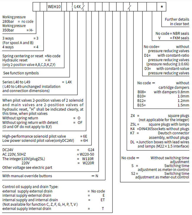
4/3, 4/2 and 3/2 directional valves of pilot operated
Type WEH 10, 16, 25 and 32
Features
– Valves used to control the start, stop and direction of a fluid
flow
– Electro-hydraulic operation (WEH)
– Porting pattern conforms to DIN 24 340 form A,ISO 4401 and
CETOP-RP 121 H
– Wet pin DC or AC solenoids, optional
– Hand override, optional
– Electrical connections as an individual or central connection
– Spring or pressure centered, spring or hydraulic offset.
Function and configurations
Valves of type WEH are directional spool valves with
electro-hydraulic operation. They control the start, stop and
direction of a flow.
Solenoid valves used for pilot control are with wet AC or DC
solenoid available; Main valves apply spring centering and spring
reset or hydraulic centering and hydraulic reset; with or without
Switching time adapters; with or without stroke regulators for main
valves; back pressure valves may be installed in main valves;
throttle may be installed; pressure reducing valves may be
installed when working pressure exceeds 250bar.
The valve mainly consists of main valve body(1), main valve
spool(2), one(or two)reset spring (3) with one(or two) pilot
solenoid valve of solenoid. Main valve spools (2) is held in the
neutral or in the initial position either by the springs or by
means or pressure. Pilot solenoid valves (4) may select wet-type AC
or
DC solenoids (5) and pilot solenoid valves are able to control the
switching of main valves.
There are four patterns on supply and drain of control oil, see the
function diagram.
Following are descriptions of various types of valves:
1. Main valves are 4/3-way directional valve with spring centering
of the control spool.
Main valve spool (2) is held in the neutral position by means of
two return springs. And two spring chambers (6) are connected with
tank through pilot solenoid valves.
When one of the two ends of the main control spool (2) is
pressurized with pilot pressure, the spool is moved to the switched
position. The required ports in the valve are then opened to flow.
When the pilot pressure is removed, the spring on the opposite side
to the pressurized spool area causes the spool to return to its
neutral or initial position.

Structure chart of spring centering electro-hydraulic directional
valve
1- Main valve body
2- Main valve spool
3- Reset spring
4- Pilot solenoid valve
5- Solenoid
6- Spring chamber
7- Control oil inlet passage
8-Manual button
2. Main valves are 4/3-way directional valve with pressure
centering of the main control spool, type 4WEH...H
The main control spool (2) in the main valve is held in the neutral
position by pressurization of the two end faces. A centering sleeve
(9) is supported in the housing and holds the spool in position.
By removing the pressure from one of the spool ends, the main
control spool (2) is moved to the shifted position.
The unloaded spool area displaces the returning pilot oil via the
pilot valve into the tank (external connection).

Structure chart of electro-hydraulic directional valves of
hydraulic pressure centering
1- Main valve body
2- Main valve spool
3- Spring
4- Pilot solenoid valve
5- Solenoid
6- Spring chamber
7- Control oil inlet passage
8- Manual button
9- Centering sleeve
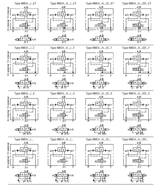
2/4 way directional valves
( this kind of valve has four different structures and Types)
1. Type WEH.../...
This kind of pilot valve and main valve have a reset spring each,
resetting by spring force.
2. Type WEH...H.../...
This kind of valve has a reset spring, making pilot valve spool
stay in initial position. Main valve spools change directions under
effect of pressure oil.
3. Type WEH...H.../O...
This kind of valve has two solenoids. There are no reset springs in
pilot valves and main valves, thus using solenoids and pressure oil
to make pilot valves and main valve spools change directions.
Therefore, at least one solenoid shall be under working sate.
4. Type WEH...H.../OF...
This kind of valve has two solenoids and locators which makes pilot
valve spools stay in working position (impulse valves). Main valve
spools have no locating devices, moving downward to corresponding
working positions under effect of pressure oil.
Structure 2, 3 and 4 aforesaid are hydraulic reset. Main valve
spools can stay in the working position only under the effect of
pressure oil.
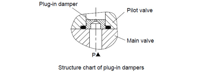
Throttle insert:
The use of a throttle insert is required if the pilot oil supply in
the P channel of the pilot valve is to be limited. This throttle is
inserted in the P channel of the pilot valve.
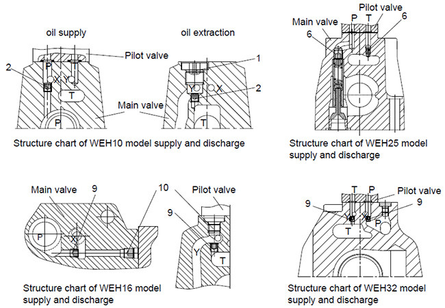
Pilot oil supply:
1. Type WEH10
(1) Conversion between internal supply and external supply:
P channel on the top of main valve bodies with M6 bolt (2) is
external supply and with M6 bolt (2) dismounted is internal supply.
(2) Conversion between internal drain and external drain:
Dismounting plug screws (1) and installing M6 bolt (2) is external
drain; dismounting M6 bolt(2) is internal drain.
2. Type WEH16
(1)Conversion between internal supply and external supply:
Dismounting plug screw (10) form P channel on the side surface of
main valves and installing M6 bolt (9) is internal supply.
Dismounting M6 plug bolt (9) is internal supply.
(2)Conversion between internal drain and external drain:
Dismounting plug screw (10) form T hole on the top of main valves
and installing M6 plug bolt (9) is internal drain. Dismounting M6
bolt (9) is external drain.
3. Type WEH25
(1)Conversion between internal supply and external supply:
P channel on the top of main valve bodies with M6 bolt (6) is
external supply and with M6 bolt (6) dismounted is internal supply.
(2)Conversion between internal drain and external drain:
Dismounting plug bolt (6) form T hole on the top of main valves and
installing M6 plug bolt (9) is internal drain. Dismounting M6 bolt
(9) is external drain.
4. Type WEH32
(1)Conversion between internal supply and external supply:
Dismounting plug screw (9) form P hole on the undersurface of main
valves and installing M6 bolt (9) is internal supply. Dismounting
M6 plug bolt (9) id internal supply.
(2)Conversion between internal drain and external drain:
Dismounting plug screw (9) form T hole on the top of main valves
and installing M6 plug bolt (9) is internal drain. Dismounting M6
bolt (9) is external drain.
Attention:
X port on base plates must be blocked when internal supply occurs
and Y port on base plates must be blocked when internal drain
occurs.
Switching time adjustment:
In order to influence the switching time of the main valve a double
throttle check valve has to be fitted between pilot valves and main
valves to control oil supply from pilot valves into main valve
spools, thus adjusting the switching time of main valves.
Regulating bolt rotation clockwise, the time for switching of main
valves is long, otherwise the time is short.
The throttle check valve has two kinds: meter-in throttling and
meter-out throttling. If there is a need of changing meter-in
throttling into meter-out throttling, just install the valve after
rotating 180.around the longitudinal axis again and then install pilot valves.
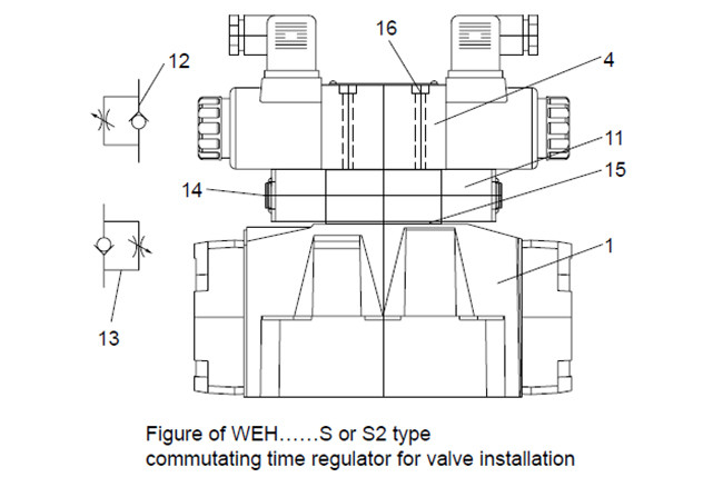
1- Main valve
4- Pilot valve
11- Switching time regulator (Z2FS6)
12- Meter-out throttling
13- Meter-in throttling
14- Adjustable bolt
15- Seal ring support plate
16- Set screw M5×L GB/T70.1-10.9 grade, the length of L is
determined by height stacked, tightening torque 8.9 Nm.
Pressure reducing valves:
The pressure reducing valve (8) must be used it the pilot pressure
is higher than 250 bar (for type 4WEH 22 ...: 210 bar).Pressure
reducing ratio of constant-ratio pressure reducing valves
(D1)1:0.66.
Pressure reducing pressure of constant-ratio pressure reducing
valves shall not exceed 40bar.
Minimum control pressure of technical specifications shall improve
1/0.66=1.515 after installing bottom plate pressure reducing
valves.
Constant-ratio pressure reducing valves shall not be used when
controlling internal oil drain and using back pressure valves
(P0.45) with control pressure decreased to 3bar.

1- Main valve
4- Pilot valve
11- Switching time regulator
17- Pressure reducing valve
18- Bolt M5×L GB/T70.1-10.9
Back pressure valve:
Valves controlling oil inner supply with unloading passages, such
as C, Z, G, H, P, S, T and V, in valves with zero pressure
circulation and internal pilot oil supply, a back pressure valve
(9) must be installed in the P-channel of the main valve to build
up the minimum pilot pressure. The pressure differential of the
back pressure valve must be added to the pressure differential of
the main valve (see characteristic curves) in order to determine
the actual value. The opening pressure of this valve is approx. 4.5
bar. NG10 valves do not have back pressure valves.

19- Back pressure valve
20- Main valve
21- Control oil chamber(X)
22- Connecting plate
Specifications
Note:
- For function of WEH10 such as C,Z,F,G,H,P,T,V , etc., if applying
control oil internal sup, please try to use external add enough
back pressure on return port T( port Y shall not have back
pressure) to ensure valves can reverse properly.
- Pressure reducing valves shall be applied when control pressure
exceeds 250bar.

Note:
- For function of WEH16-32 such as C, Z, F, G, H, P, T, V, etc., if
applying control oil internal sup, please try to use external add
enough back pressure on return port T( port Y shall not have back
pressure) to ensure valves can reverse properly.
- Pressure reducing valves shall be applied when control pressure
exceeds 250bar.
Symbols
Detailed and simplified symbols for 3-position valves
Valves with spring centered Valves with hydraulic centered
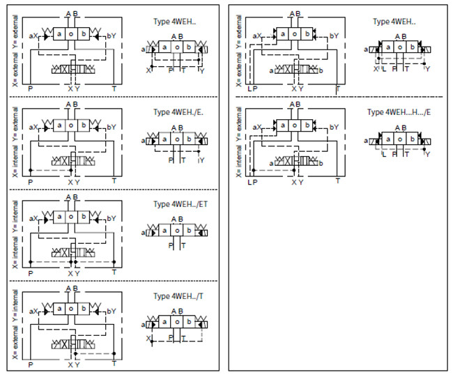
Valves with spring offset (At position A or B of 2-position valve
derived from 3-position)

Valves with hydraulic offset (At position A or B of 2-position
valve derived from 3-position)

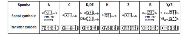
Spools of 3-position valves
3-position valve 2-positon derivative from 3-position

Detailed and simplified symbols for 2-position valves
Spools of 2-position valves
Technical details
1. Hydraulic section
1). WEH10 Type electro-hydraulic directional valve
Maximum working pressure: P, A, B (bar) | Type H-WEH10 | Type WEH10 |
| 350 | 280 |
| Port T (bar) | With external pilot oil drain | 315 |
| With internal pilot oil drain | DC210 AC160 |
| Port Y (bar) | With external pilot oil drain | DC210 AC160 |
Min. control pressure (bar) | With external pilot oil supply With internal pilot oil supply (not
apply to C, Z, F, G, H, P, T, V) | 3-position valve 10 |
| Spring-return 2-position valve 10 |
| Hydraulic-return 2-position valve 7 |
| With internal pilot oil supply ( apply to C, Z, F, G, H, P, T, V ) | 6.5 |
| Max. control pressure (bar) | 250 |
| Hydraulic fluid | Mineral oil, phosphate oil |
| Temperature range of Hydraulic fluid (〇C) | -30 to+80 (NBR seals) |
| -20 to+80 (FKM seals) |
| Viscosity range (mm2/s) | 2.8 to 500 |
| Switching pilot oil volume (cm3) | 3-position valve 2.04 2-position valve 4.08 |
| Switching times (= Valve switching time from the neutral position
to the switched position) (AC and DC) |
| Control pressure (bar) | 70 | 140 | 210 | 250 |
| AC | DC | AC | DC | AC | DC | AC | DC |
| 3-position valve (ms) | 30 | 65 | 25 | 60 | 20 | 55 | 15 | 50 |
| 2-position valve (ms) | 35 | 80 | 30 | 75 | 25 | 70 | 20 | 65 |
| Switching times (= Valve switching time from the neutral position
to the switched position) |
| 3-position valve (ms) | 30 |
| 2-position valve (ms) | 35 | 40 | 30 | 35 | 25 | 30 | 20 | 25 |
| Flow of shortest switching time (L/min) | About 35 |
| Installation position | HC, HD, HK, HZ and HY of hydraulic return shall installed
horizontally. The rest are arbitrary |
| Weight (kg) | Single solenoid valve | 6.7 |
| Double solenoid valve | 7.1 |
| Switching time regulator | 1.0 |
| Reducing valve | 0.5 |
2). WEH16 Type electro-hydraulic directional valve
Maximum working pressure: P, A, B (bar) | Type H-...WEH16... | Type ... WEH16... |
| 350 | 280 |
| Port T (bar) | With external pilot oil drain | 250 | 250 |
| With internal pilot oil drain | DC 210 | AC 160 |
Hydraulic-centering 3-position valve With internal pilot oil drain is impossible |
| Port Y (bar) | With external pilot oil drain | DC210 | AC160 |
Min. control pressure (bar) | With external pilot oil supply With internal pilot oil supply With internal pilot oil supply | 3-position valve 14 Spring-return 2-position valve 14 Hydraulic-return 2-position valve 14 |
| When applying prepressing or the flow is large correspondingly
,enginery of spool valve is 4.5 as C, Z, F, G, H, P, S, T and V |
| Max. control pressure (bar) | 250 |
| Hydraulic fluid | Mineral oil, phosphate oil |
| Temperature range of Hydraulic fluid(℃ ) | -30 to + 80 (NBR seals) |
| -20 to + 80 (FKM seals) |
| Viscosity range (mm2/s) | 2.8 to 500 |
| Switching pilot oil volume |
| - Spring-centering 3-position valve(cm3) | 5.72 |
| -2-position valve(cm3) | 11.45 |
| Hydraulic-centering 3-position valve |
| -From"0"position to working position "a"(cm3) | 2.83 |
| -From working position "a" to "0"position (cm3) | 2.9 |
| -From "a" position to working position "b"(cm3) | 5.72 |
| -From working position "b" to "0"position (cm3) | 2.83 |
| * Switching times (= Valve switching time from the neutral position
to the switched position) (AC and DC) |
| Control pressure (bar) | 50 | 150 | 250 |
| AC | DC | AC | DC | AC | DC |
| -Spring-centering 3-position valve (ms) | 35 | 65 | 30 | 60 | 30 | 58 |
| -2-position valve (ms) | 45 | 65 | 35 | 55 | 30 | 50 |
| -Hydraulic-centering 3-position valve (ms) | a | b | a | b | a | b | a | b | a | b | a | b |
| 30 | 30 | 65 | 65 | 25 | 25 | 55 | 63 | 20 | 25 | 55 | 60 |
*Switching times (= Valve switching time from the neutral position to the switched position) |
| -Spring-centering 3-position valve (ms) | 30 |
| -2-position valve (ms) | 45 | 45 | 35 | 35 | 30 | 30 |
| -Hydraulic-centering 3-position valve (ms) | a | b | a | b | a | b | a | b | a | b | a | b |
| 20 | 20 | 20 | 20 | 20 | 20 |
| Installation position | C, D, K, Z, Y Type hydraulic-return valves are installed horizontally, the rest can be installed arbitrarily |
Flow of shortest switching time (L/min) | About 35 |
Weight of the valve (kg) | About 9.5 |
3). WEH25 Type electro-hydraulic directional valve
Maximum working pressure: P, A, B (bar) | Type H-...WEH25... | Type ... WEH25... |
| 350 | 280 |
| Port T (bar) | With external pilot oil drain | 250 | 250 |
| With internal pilot oil drain | DC 210 | AC 160 |
Hydraulic-centering 3-position valve With internal pilot oil drain is impossible |
| Port Y (bar) | With external pilot oil drain | DC210 | AC160 |
Min. control pressure (bar) | With external pilot oil supply With internal pilot oil supply | Spring-centering 3-position valve 13 |
| Hydraulic-centering 3-position valve 18 |
| Spring-return 2-position valve 13 |
| Hydraulic-return 2-position valve 8 |
| With internal pilot oil supply | When applying prepressing or the flow is large correspondingly
,enginery of spool valve is 4.5 as C,Z,F,G,H,P,S,T and V |
| Max. control pressure (bar) | 250 |
| Hydraulic fluid | Mineral oil, phosphate oil |
| Temperature range of Hydraulic fluid(℃ ) | -30 to + 80 (NBR seals) |
| -20 to + 80 (FKM seals) |
| Viscosity range (mm2/s) | 2.8 to 500 |
| Switching pilot oil volume |
| - Spring-centering 3-position valve(cm3) | 14.2 |
| -2-position valve(cm3) | 28.4 |
| Hydraulic-centering 3-position valve |
| -From"0"position to working position "a"(cm3) | 7.15 |
| -From working position "a" to "0"position (cm3) | 7.0 |
| -From "a" position to working position "b"(cm3) | 14.15 |
| -From working position "b" to "0"position (cm3) | 5.73 |
| *Valve switching time from the neutral position to the switched
position ( DC and AC solenoid) |
| Control pressure (bar) | 50 | 150 | 210 | 250 |
| AC | DC | AC | DC | AC | DC | AC | DC |
| -Spring-centering 3-position valve (ms) | 50 | 85 | 40 | 75 | 35 | 70 | 30 | 65 |
| -2-position valve (ms) | 120 | 160 | 100 | 130 | 85 | 120 | 70 | 105 |
| -Hydraulic-centering 3-position valve (ms) | a | b | a | b | a | b | a | b | a | b | a | b | a | b | a | b |
| 30 | 35 | 55 | 65 | 30 | 35 | 55 | 65 | 25 | 30 | 50 | 60 | 25 | 30 | 50 | 60 |
| *Valve switching time from the neutral position to the switched
position |
| -Spring-centering 3-position valve (ms) | 40 |
| -2-position valve (ms) | 120 | 125 | 95 | 100 | 85 | 90 | 75 | 80 |
| -Hydraulic-centering 3-position valve (ms) | a | b | a | b | a | b | a | b | a | b | a | b | a | b | a | b |
| 20 | 35 | 30 | 35 | 30 | 35 | 30 | 35 | 30 | 35 | 30 | 35 | 30 | 35 | 30 | 35 |
| Installation position | C,D,K,Z,Y Type hydraulic-return valves are installed horizontally, the rest can be installed arbitrarily |
Flow of shortest switching time (L/min) | About 35 |
Weight of the valve (kg) | About 18 |
4). WEH32 Type electro-hydraulic directional valve
Maximum working pressure: P, A, B (bar) | Type H-...WEH32... | Type ... WEH32... |
| 350 | 280 |
| Port T (bar) | With external pilot oil drain | 250 | 250 |
| With internal pilot oil drain | DC 210 | AC 160 |
Hydraulic-centering 3-position valve With internal pilot oil drain is impossiblee |
| Port Y (bar) | With external pilot oil drain | DC210 | AC160 |
Min. control pressure (bar) | With external pilot oil supply With internal pilot oil supply With internal pilot oil supply | 3-position valve 8.5 Spring-return 2-position valve 10 Hydraulic-return 2-position valve 5 |
| When applying prepressing or the flow is large correspondingly
,enginery of spool valve is 4.5 as C, Z, F, G, H, P, S, T and V |
| Max. control pressure (bar) | 250 |
| Hydraulic fluid | Mineral oil, phosphate oil |
| Temperature range of Hydraulic fluid(℃ ) | -30 to + 80 (NBR seals) |
| -20 to + 80 (FKM seals) |
| Viscosity range (mm2/s) | 2.8 to 500 |
| Switching pilot oil volume |
| - Spring-centering 3-position valve(cm3) | 29.4 |
| -2-position valve(cm3) | 58.8 |
| Hydraulic-centering 3-position valve |
| -From"0"position to working position "a"(cm3) | 14.4 |
| -From working position "a" to "0"position (cm3) | 15.1 |
| -From "a" position to working position "b"(cm3) | 29.4 |
| -From working position "b" to "0"position (cm3) | 14.4 |
| *Valve switching time from the neutral position to the switched
position ( DC and AC solenoid) |
| Pilot valve pressure (bar) | 50 | 150 | 250 |
| AC | DC | AC | DC | AC | DC |
| -Spring-centering 3-position valve (ms) | 65 | 80 | 50 | 90 | 35 | 105 |
| -2-position valve (ms) | 100 | 130 | 75 | 100 | 60 | 115 |
| -Hydraulic-centering 3-position valve (ms) | a | b | a | b | a | b | a | b | a | b | a | b |
| 55 | 60 | 100 | 105 | 40 | 45 | 85 | 95 | 35 | 40 | 85 | 95 |
| *Valve switching time from the neutral position to the switched
position |
| -Spring-centering 3-position valve (ms) | DC:50, AC:60) |
| -2-position valve (ms) | 115 | 90 | 35 | 70 | 65 | 65 |
| -Hydraulic-centering 3-position valve (ms) | a | b | a | b | a | b | a | b | a | b | a | b |
| 30 | 50 | 30 | 40 | 60 | 75 | 30 | 30 | 105 | 140 | 50 | 50 |
| Installation position | C, D, K, Z, Y Type hydraulic-return valves are installed
horizontally, the rest can be installed arbitrarily |
Flow of shortest switching time (L/min) | About 50 |
Weight of the valve (kg) | About 36 |
*Switching time refers to time from drawing of solenoid of pilot
valve to full opening of main valve.
2. Electrical data
| Type of voltage | Direct voltage | Alternating voltage |
| Voltage (allowable fluctuation of ±10%) | 12, 24, 28 1), 48, 96 110,205,220 | 110,127,220 |
| Power(W) | High-performance solenoid valve 30 | Low-powered solenoid valve 16 | |
| Holding power (VA) | | 50 |
| Starting power (VA) | | 220 |
| Operating state | Continuous |
| Temperature range of environment (℃) | 〜+50 |
| Temperature range of coil (C) | 〜+150 |
| Protection class to DIN40050 | IP65 |
1)Usually used for engineering machinery.
For other voltage, please consult the company.


