3/2 and 4/2 directional poppet valve with solenoid actuation
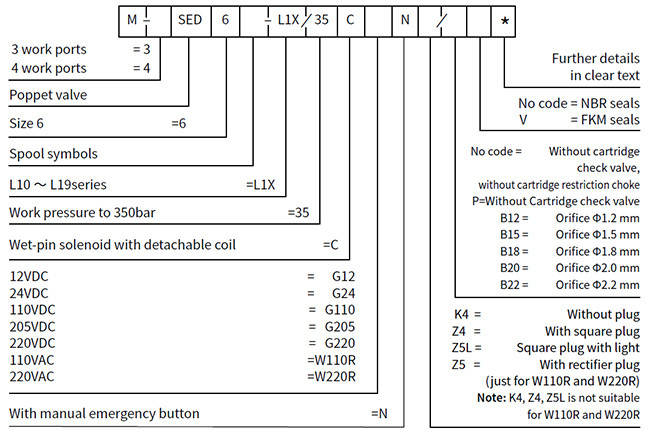
Type M-.SED6...L1X
Features
– Direct operated directional poppet valve with solenoid actuation
– Mounting face as per DIN24 340 A ISO 4401 and CETOP-RP 121H
– Closed port is leak-free isolated
– Keep switch flexibility under high pressure
– Pressure-tight chamber does not need to be opened when changing
of the coil
– Solenoid coil can be rotated through 90°
– With optional concealed manual override
Function and configuration
·M-3SED6 are directional poppet valves with solenoid actuation. They
control the start, stop and direction of flow.
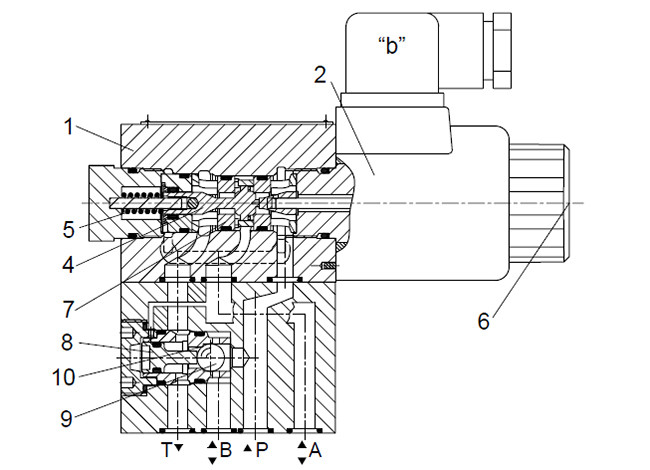
The directional valve mainly consist of housing (1), solenoid (2),
valve seats (7) and (11) and closing element (4). With the help of
manual override (6) the valves can be operated without energization
of the solenoid.
General principle (3/2 directional poppet valve):
The initial position of the valve (normally open "UK" or normally
closed "CK") is determined by the arrangement of the spring (5).
Chamber (3) behind closing element (4) is connected to port P and
closed towards port T. The valve is therefore pressure balanced
with regard to the actuating forces (solenoid and spring).
Due to the special closing element (4) ports P, A and T can be
pressurized to the maximum operating pressure (350 bar), and the
flow can be directed in both directions (see symbols)!
In the initial position, closing element (4) is pressed by the
spring (5) onto seat (11), in the shifted position, it is pushed by
the solenoid (2) onto seat (7). The flow is leak free blocked.

·M-4SEW6 4/2 directional poppet valve
In conjunction with a sandwich plate, the Plus-1 plate, under the
3/2 directional poppet valve, the function of a 4/2 directional
poppet valve can be realized.
1). Initial position:
The main valve is not operated. Spring (5) holds closing element
(4) on seat (11). Port P is blocked, and A is connected to T. A
pilot line is provided from A to the large area of pilot spool (8),
which is therefore unloaded to tank.
The pressure applied via P now shifts ball (9) onto seat (10).
This opens the connection from P to B and A to T.
2). Transition position:
When the main valve is operating, closing element (4) is shifted
against spring (5) and pressed onto seat (10). This results in
closing of port T, while P, A and B are briefly connected.
3). Switching position:
P is connected to A. Since the pump pressure acts via A on the
large area of pilot spool (8), ball (9) is pressed onto seat (12).
B is therefore connected to T, and P to A. Ball (9) in the Plus-1
plate has a "positive overlap".
·Cartridge type orifice plug(model M-.SED6.L1X/...)
For the work status of the valve during switching process, the flow
may be over the value permitted by the valve performance limit
curve; in this case, a cartridge orifice plug is necessary.
The orifice plug is installed in port P.
·Cartridge check valve (model M-.SED6.L1X/...)
Cartridge check valve allows the oil flows from P to A freely with
no leaks from A to P.
One-way valve is installed on port P.

Spool symbols

Specification
Technical data
| Installation position | Optional |
| Environment temperature | ℃ | -30 to +50 (NBR seal) |
| -20 to +50 (FKM seal) |
| Weight | 2/2,3/2 directional poppet valve | Kg | 1.5 |
| 4/2 directional poppet valve | Kg | 2.3 |
| Max operation pressure | bar | 350 |
| Max flow | L/min | 25 |
| Hydraulic fluid | Mineral oil suitable for NBR and FKM seal |
| Phosphate ester for FKM seal |
| Hydraulic fluid temperature range | ℃ | -30 to +80 (NBR seal) |
| -20 to +80 (FKM seal) |
| Viscosity range | mm2/s | 2.8 to 500 |
| Degree of contamination | Maximum permissible degree of fluid contamination: Class 9. NAS
1638 or 20/18/15, ISO4406 |
Electrical data
| Voltage type | DC | AC |
| Available voltage | V | 12, 24, 110, 205, 220 | 110, 220 (Only by Z5 rectifier plug ) |
| Voltage tolerance (nominal voltage) | % | +10~-15 |
| Power consumption | W | 30 |
| Duty cycle | 100% |
| Switching time to ISO 6403 (installation position: Solenoid
installed horizontally) |
| Pressure bar | Flow L/min | DC | AC + rectifier |
| On/ms (without oil tank pressure) | Off/ms | On/ms (without oil tank pressure) | Off/ms |
| UK | CK | D | Y | UK, CK | D, Y | U | C | D | Y | U, C | D, Y |
| 70 | 25 | 45 | 40 | 50 | 50 | 10 | 15 | 45 | 40 | 45 | 40 | 40 | 40 |
| 140 | 25 | 60 | 40 | 50 | 50 | 10 | 15 | 55 | 40 | 55 | 40 | 40 | 40 |
| 210 | 25 | 60 | 45 | 60 | 50 | 10 | 15 | 60 | 45 | 60 | 45 | 40 | 40 |
| 280 | 25 | 60 | 45 | 60 | 50 | 10 | 15 | 65 | 45 | 65 | 45 | 40 | 40 |
| 315 | 25 | 65 | 45 | 65 | 50 | 10 | 15 | 65 | 45 | 65 | 45 | 40 | 40 |
| 350 | 25 | 65 | 45 | 65 | 50 | 10 | 15 | 65 | 45 | 65 | 45 | 40 | 40 |
| Note: switching time is related to flow direction (P to A / A to T);
there may be deviation for reverse flow |
| Switching frequency | times/h | Up to 15000 |
| Type of protection to DIN 40050 | IP65 |
| Max coil temperature | ℃ | +150 |
Note: When making the electrical connection, properly connect the
protective conductor.
Unit dimensions
·M-3SED6ck uk -L1X/...solenoid directional poppet valve

1 Solenoid
2 Manual emergency button
3 Plug as per DIN43650 (can rotate for 90 degrees)
4 Space required to remove cable socket
5 O-ring 9.25×1.78 for port P, T, A and B
6.1 Plug for M-3SED6UK-L1X/..
6.2 Plug for M-3SED6CK-L1X/..
7 Name plate.
8 Space required to remove coil
9.1 M-3SED6UK-L1X/.. total length
9.2 M-3SED6CK-L1X/.. total length
10 Fixing nut, Tightening torque MA=4Nm
11 Oil port B of the valve is a blind bore.
12 Valve fixing screw:
M5×50 GB/T70.1-10.9
Tightening torque MA=8.9Nm
It must be ordered separately, if connection plate is needed. Type:
G341/01(G1/4), G341/02(M14×1.5)
G342/01(G3/8), G342/02(M18×1.5)
G502/01(G1/2), G502/02(M22×1.5)
·M-4SED6D Y -L1X/..solenoid directional poppet valve

1 Solenoid
2 Manual emergency button
3 Plug as per DIN43650 (can rotate for 90 degrees)
4 Space required to remove cable socket
5 O-ring 9.25×1.78 for port P, T, A and B
6.1 Plug for M-4SED6D-L1X/..
6.2 Plug for M-4SED6Y-L1X/..
7 Name plate.
8 Space required to remove coil
9.1 M-4SED6D-L1X/.. total length
9.2 M-4SED6Y-L1X/..total length
10 Fixing nut, Tightening torque MA=4Nm
11 Oil B of the valve is a blind bore.
12 Valve fixing screw:
M5×50 GB/T70.1-10.9
Tightening torque MA=8.9Nm
It must be ordered separately, if connection plate is needed. Type:
G341/01(G1/4), G341/02(M14×1.5)
G342/01(G3/8), G342/02(M18×1.5)
G502/01(G1/2), G502/02(M22×1.5)


