2/2, 3/2 and 4/2 directional poppet valve with solenoid actuation
Type M-.SEW6...L3X
Features
- Direct-acting solenoid direction shut-off valve
- Mounting face as per DIN24 340 A
ISO 4401 and CETOP-RP 121H
- Free of leakage
- Switching flexibility in high-pressure state
- Replace the coil, can take pressure operation
- Solenoid coil can rotate for 90 degrees
- Manual emergency operation available
Function and configuration
M-SEW6 direction valve is a solenoid shut-off directional poppet
valve for control oil opening, stop and flow direction.
Two-position TEE solenoid directional poppet valve consists of
valve body (1), Solenoid (2), and valve element (3). Connect a
superposition plate below the two-position TEE solenoid directional
poppet valve to connect valve body (4), it becomes into
two-position four-way direction poppet valve. The manual emergency
button (5) can be used to operate the valve when the Solenoid is
not powered on.
· M-3SEW6 two-position TEE solenoid directional poppet valve
1). Initial position:
when the Solenoid is not energized, pretention of spring (6) keeps
valve element (3) on valve seat (7) on the left, so that oil port P
is connected to A and oil port T is closed.
2). Switching position:
after the Solenoid is energized, through angular lever (9) and ball
(10), the force of Solenoid (2) acts on push rod (11) of the
two-side seal, thus to push valve element (3) and maintain it on
right valve seat (8), causing oil port P closed and oil port A
connected to port T. Since push rod (11) and valve element (3),
acted by the inlet pressure, is in a balance state of axial
hydraulic pressure, the valve can be used when pressure is up to
420bar.
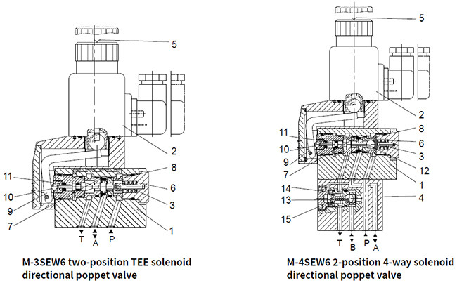
· M-4SEW6 2-position 4-way solenoid directional poppet valve
1). Initial position:
when the Solenoid is not energized, pretention of spring (6) keeps
valve element (12) on valve seat (8) on the right, oil port P is
closed and port A connected to T; pressure oil supplied from oil
port P push steel ball (13) to valve seat (14), upon which oil port
P is connected to B and A connected to T; besides, a control oil
line is connected from oil port A acts on the big area of control
piston (15), which can be used for unloading to oil tank.
2). Switching position:
after the Solenoid is energized, oil port P is connected to A;
pressure oil from the pump goes through the control oil line
connected from port A and acts on the big area of control piston
(15); steel ball (13) is pushed to the other side of valve seat
(14), thus oil port P is connected to A and B connected to T.
· Cartridge restriction choke (model M-.SEW6.L3X/.../B...)
To restrict flow through the valve, a restriction choke can be
installed.
Restriction choke is installed on port P.
· Cartridge type one-way valve (model M-.SEW6.L3X/.../P)
Cartridge type one-way valve allows oil flow in from port P and it
is closed for reverse flowing.
One-way valve installed on port P.

Spool symbols

Specification

Technical data
| Installation position | Optional |
| Environment temperature | ℃ | -30 to +50 (NBR seal) |
| -20 to +50 (FKM seal) |
| Weight | Two two-way Solenoidic directional valve | Kg | 1.5 |
| Two three-way Solenoidic directional valve | Kg | 1.5 |
| Two four-way Solenoidic directional valve | Kg | 2.3 |
| Max operation pressure | Port P, A, B | bar | 420 |
| Port T | 100 |
| Max flow | L/min | 25 |
| Fluid | Mineral oil suitable for NBR and FKM seal |
| Phosphate ester for FKM seal |
| Fluid temperature range | ℃ | -30 to +50 (NBR seal) |
| -20 to +50 (FKM seal) |
| Viscosity range | mm2/s | 2.8 to 500 |
| Degree of contamination | Maximum permissible degree of fluid contamination: Class 9. NAS
1638 or 20/18/15, ISO4406 |
Electrical data
| Voltage type | DC | AC |
| Available voltage | V | 12, 24, 110, 205, 220 | 110, 220 (Only by Z5 rectifier plug ) |
| Allowed voltage (deviation) | % | +10~-15 |
| Required power | W | 30 |
| Continuous power-on time | % | 100 |
| Switching time in compliance with ISO 6403 |
| Pressure bar | Flow L/min | DC | AC50HZ |
| on/ms (without oil tank pressure) | off/ms | on/ms (without oil tank pressure) | off/ms |
| U | C | D | Y | U, C | D, Y | U | C | D | Y | U, C | D, Y |
| 140 | 25 | 25 | 30 | 25 | 30 | 10 | 10 | 30 | 40 | 30 | 40 | 35 | 35 |
| 280 | 25 | 25 | 30 | 25 | 30 | 10 | 10 | 35 | 45 | 35 | 45 | 40 | 40 |
| 320 | 25 | 25 | 35 | 25 | 35 | 10 | 10 | 35 | 50 | 35 | 50 | 40 | 40 |
| 420 | 25 | 25 | 35 | 25 | 35 | 10 | 10 | 40 | 50 | 40 | 50 | 50 | 50 |
| Switching frequency | Time/h | Up to 15000 |
| IP rating as per DIN 40050 | IP65 |
| Max coil temperature | ℃ | +150 |
Note: for electrical connection, protective wire shall be earthed as
required.
Unit dimensions
·2-position 2-way, 2-position 3-way solenoid directional poppet
valve

1 Solenoid
2 Manual emergency button
3 Plug as per DIN43650 (can rotate for 90 degrees)
4 Remove space needed for Solenoid coil.
5 Lock nut, tightening torque MA=4Nm
6 Remove space
7 Name plate.
8. Oil port A and B use O ring 9.25×1.78, P uses O-ring 10×2
9. Valve securing screw: M5×45 GB/T70.1- class 10.9, Tightening
torque MA=8.9Nm
10 2-position 2-way directional valve has oil port A and B which
are blind holes;
3/2 directional poppet valve has oil port A and B which are blind
holes.
·2-position 4-way solenoid directional poppet valve

1 Solenoid
2 Manual emergency button
3 Plug as per DIN43650 (can rotate for 90 degrees)
4 Remove space needed for Solenoid coil.
5 Lock nut, tightening torque MA=4Nm
6 Remove space
7 Name plate.
8 Connecting valve body
9 Oil port A and B use O ring 9.25×1.78, P uses O-ring 10×2
10 Valve securing screw hole, M5×90 GB/T70.1-10.9, Tightening
torque MA=8.9Nm


